
4 Mistakes to Avoid when Working with Legacy Drawings

Every year at Protomatic, we see and review thousands of blueprints during our quoting process. Our goal for each is the same: To review even the smallest detail of the blueprint in a manner that allows us to accurately quote and manufacture the part.
To accomplish this, each quote received at Protomatic is reviewed by a multi-functional team with one or more representatives from Sales, Engineering, Manufacturing, Quality, and Management. Each group brings a different view and prospective to the review process. But by challenging and learning from each other, we are able to determine the best way to manufacture the part to blueprint specs, while also achieving quality and business requirements.
Lately however, we have observed some consistent problems with the prints we receive. Following are some of the mistakes we see most often, and tips that design engineers can find helpful in alleviating those print mistakes, and improving part and product quality.
- 1. Print vs solid model in disagreement
Description: As a manufacturer, we typically receive two forms of data. They are the “Print” that is the hard copy Blue Print, and the “Math Data” —the universal electronic file that comes directly from the CAD program.
Application: All CAD based drawing.
Issue: In many contracts, we receive both sets of information and sometimes there is a difference. To improve manufacturing accuracy, at Offer/Tender stage we often ask the customer if we are we making, the Print or CAD model (AKA Math Data). In most cases the contract is based on the “Blue Print”. But in effort the reduce cost, the customer-provided math data is used to quote, program, and inspect the manufactured parts.
Manufacturing Implications: In an effort the reduce cost, the customer-provided math data is used to program the manufactured parts. As well as the CAD Math Data may be used for missing dimensions.
Quality Implications: In effort the reduce cost, the customer-provided math data is used to program the CMM for inspecting the manufactured parts.
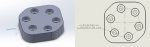
Recommendation: Review “Math Data (CAD)” to “Print”. About 3% of provided Prints/Math Data have at least one error from minor issues like unconnected surfaces or dimensional differences. To demonstrate, here is an example:
-
-
- Typical dimensional mismatch: CAD Math Data has the C’Bore at 0.190″ deep.
- Print states 0.210″. Tolerance is 0.005″. What is needed for the application?
-
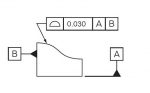
- 2. Profiles of line or surface GD & T usage
Description: Profile of a Line measures the maximum deviation from the theoretical ideal surface. Profile of a surface is the same as a line but in two axis. The value represents the distance of the band limits.
Applications: Some applications need this requirement, like a propeller or turbine blade. But a simple bracket or plates should not use due to increased manufacturing and inspection cost.
Manufacturing Implication: Higher cost of Inspection. This requires a scanning of the Line or scanning of the Surface.
Quality Implication: This is simple process with the correct equipment, but the equipment is expensive. Additionally, CMM scanning takes more time, costing more. While laser scanning may be faster, it will typically be less accurate.
Recommendation: This is a great GD&T Symbol because it uses the 4 fundamental Elements of GD&T, (Size, Location, Orientation and Form), but use sparingly because it adds cost to inspection.
- 3. Cosmetic requirements and finishes
Description: Special attention should be defining the location of acceptable holding points for anodizing, painting and plating. There are small but noticeable contact points for many finishing operations.
Applications: Cosmetic, end user and medical serialization applications.
Manufacturing Implication: Rack mark location may be in undesirable location or may change from batch to batch.
Quality Implication: This helps define, and makes more consistent and better quality parts. On some parts, the rack mark location will not have the finish, so additional touch-up like Chem Film (Mil-C-5541) or other secondary operation should be specified.
Recommendation: Define racking location for finishes. This is a great addition to the print and does not add to cost.
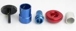
Typical Racking Marks for Anodize Type II.
- 4. Should “Dimensions Apply Statement” come before or after finishing
Description: Absence of “Dimensions Apply” statement in Title Block default or specified note. Most standards such as Dimensioning and Tolerance Standard ASME Y14.5-2018 state that “Dimensions Apply” before or after finish must be stated on the print. Many times, the assumption that it is after finish, but it is not a default or can be assumed. This statement on a print is considered to be a customer-specific requirement and must be defined.
Applications: Any part that has a finishing operation.
Manufacturing Implications: Protomatic will create process drawings that compensate for heat treat, anodizing, plating, painting and any finish that has thickness or dimensional change. This is critical for manufacturing process drawing.
Quality Implications: Parts that have thick finish, like paint, can have fit issues. Also, critical bores should be masked of finish if possible. The concern is most processes have large thickness variations, paint being the worst, although plating and anodizing can vary thickness significantly. Please consult with finisher or Protomatic for more information.
Recommendations: State the desired condition in the Title Block or Note. This has no cost impact but helps clarify the product requirements. Make sure to consider masking critical bores and threads. The ASME Y14.5 standard states:- 5.4.1 Plated or Coated Parts
Where a part is to be plated or coated, the drawing or referenced document shall specify whether the dimensions apply before or after plating. Examples of notes are:
(a) DIMENSIONAL LIMITS APPLY AFTER PLATING
(b) DIMENSIONAL LIMITS APPLY BEFORE PLATING
Note: For processes other than plating, substitute the appropriate term.
ASME Y14.5-2018 (older versions as well) Section 5.4.1 has no default for when Dimensional Limits apply.
- 5.4.1 Plated or Coated Parts
Saving Lives Is No Mistake
As a precision CNC machining shop with emphasis on components for the medical and aerospace industries, Protomatic realizes the importance of the smallest details in everything from blueprints to final production. Because of the critical nature of the parts we design and manufacture, the emphasis is always on “Life-Saving Precision”.

About the author: Doug Wetzel is Vice President and General Manager of Protomatic. Protomatic is a CNC precision machining shop specializing in prototype and short-run production components for the medical, aerospace and other technical industries. Because of the critical nature of the parts they design and manufacture, the emphasis is always on Life-Saving Precision.