
Best Practices for Providing CAD Math Data
Customer-provided CAD math data is critically important to manufacturing. It expedites quotations, and is used in the CAM programs to create the CNC program used to manufacture parts, and the CMM program to inspect them. Historically, Protomatic has received CAD math data from customers along with a paper print with tolerancing information.
Occasionally, there is a mismatch between the two. In this situation, the customer is contacted for clarification and the print or CAD math data is corrected for CNC and CMM programming.
One of the ways to mistake-proof the engineering process is with improved CAD math data. There are three steps to improving the data.
Step 1: Send accepted formats
Native– This is the base format of the CAD program. Protomatic is a SolidWorks user, so this is the best format to send. But, if your company does not use SolidWorks, then it’s best to translate to an industry standard and send one of the following formats:
- Parasolid, Binary file with a file extension such as *.x_t or *.x_b
- IGeS, Initial Graphics Exchange Specification (NIST), *.IGS
- DXF, Drawing Interchange Format, 2D only files, *.dxf
- STeP , Standard for the Exchange of Product model Data (new IGeS)
Once the data is sent, we move to the next step.
Step 2: Confirmation of critical parameters
Our team will occasionally ask new and existing customers a few simple but critical questions.
Are we responsible for making the “paper print” or the “math data”? Some customers specify that the paper print takes precedence over the math data. In this scenario, the CAD math data is used, and then confirmed to the paper print.
Some customers define this in their purchasing terms and conditions. But there is always a possibility of a difference between the paper print and the CAD math data. The amount of mismatches varies by industry. We experience a 20-60% mismatch between the paper print and CAD math data.
If paper prints are not provided, then we need to confirm scaling. The CAD math data, when translated, does not provide this information. We typically need to confirm one dimensional size and the basic units. Since we do not know if the original print was drawn in millimeters or inches, this protects us from making a part 25.4x too small or too big.
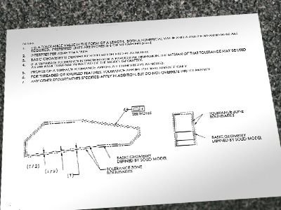
When providing only CAD math data, tolerancing is typically not provided. This requires some additional clarification to interpret the drawing for critical features. Some customers create ambiguity when adding tolerance such as “+-0.08mm, angles +/-1 deg,” so we recommend using the basic “profile feature” and interpreted to ASME Y14.5-2009. Special tolerancing instructions are available.
Step 3: Math data in nominal condition can save money
Most engineers or CAD designers draw to a design condition; some for tolerance studies, some for worst case condition for FEA analysis. But, when manufacturing and inspecting, math data must be redrawn and corrected for proper tolerancing. This is most often based on the paper print. This is where a savings could occur, because the “part” has to be redrawn to the nominal condition for all the features. This data can then be used to program the CNC machines or CMMs to inspect the part.
The redraw is focused on three basic areas: basic tolerance, advanced tolerances and basic tolerance-compensate for tolerance.
Basic tolerance
This may sound simple, but it is actually complex. Most drawings are in the design condition, meaning a feature is drawn at 1.000 inches with a tolerance of +0.000-0.005. In most CAD files, it will be drawn at 1.000 inches. In the manufacturing CAD math data, the feature should be drawn at 0.9975, in the center of the tolerance.
Advanced tolerance – compensate for L-M material conditions
“Least” and “Maximum” material condition should be accounted for on the drawing to optimize the part, manufacturing and inspection processes.
Compensate for “dimensions apply after ….”
For parts that are heat treated (both shrinkage and expansion occur depending on temper and alloy), plated, painted or anodized, the volumetric size needs to be compensated for prior to coatings. There are a lot of processes that can change dimensions. The machined part needs to be compensated because coating thickness should be adjusted if the prints are drawn to “dimensions apply after coating.” This is very important to high precision parts.
This does not solve all the problems, but it gives some insight on how CNC job shops are utilizing the CAD math data and what we go through to make your precision parts.
Better drawings mean fewer errors
Better drawings (paper or data) create fewer errors in manufacturing and inspection. Having a machinist checking the print through a manufacturing prototype process is an expensive way to correct a drawing, not to mention it is very expensive when the product needs to be remade.
Having a CNC job shop redraw corrections is also subject to some error, because information may be misunderstood or incorrectly implemented. Our focus is always on Life-Saving Precision in every part we make and your help allows us achieve that goal.
Bottom line? We’re here to support you. We are committed to making better parts through design, manufacturing, and inspection. With better CAD math data from the start, we are able to pass more savings on to you.
For more information on choosing the right CNC shop for your needs, please download our free guide, Tips for Choosing a Prototyping Machine Shop.

About the author: Doug Wetzel is Vice President and General Manager of Protomatic. Protomatic is a CNC precision machining shop specializing in prototype and short-run production components for the medical, aerospace and other technical industries. Because of the critical nature of the parts they design and manufacture, the emphasis is always on Life-Saving Precision.