The Accuracy of Legacy Drawings is Hanging by a Thread

Every year, we receive hundreds of blueprints to review as part of our quoting process. While the reviews are time-intensive, they are not only important, but essential to assuring that even the smallest details are carefully examined in a way that results in accurate quotes and precision manufacture.
Each quote received at Protomatic is reviewed by a multi-functional team with one or more representatives from Sales, Engineering, Manufacturing, Quality, and Management. Each group brings a different view and prospective to the review process. But by challenging and learning from each other, we can determine the best way to manufacture the part to blueprint specs, while also achieving quality and business requirements.
One area that seems to bring up questions and problems is blueprints for threaded components. Following are two of the most prominent issues that arise in that regard, as well as tips on improving component quality by keeping common mistakes from happening.
1. Thread Depth — call out to +-0.005’’ depth
Description: Small devices with critical holes have little space to work with. This requires controlling drilled and tapped holes to precise requirements, or holes may break out or break into other features.
Manufacturing Implication: Manufacturing planning is critical. The force of the drill point can/will make a protruding dent on the far wall. Therefore, order of operations is critical. The hole is drilled first, then the far surface is complete. Thread mill tapping is then conducted to control the thread length.
Quality Implications: Measuring the thread depth is subject to the application. Methods are based on industry. Some count physical screw length using a thread gage or designated screw with or without a limiter. Another method is by counting the number thread rotations when removing the gage and calculating based on pitch.
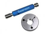
Typical GO NO-GO Plug and Ring Gage (Only one shown)
2. Thread Location — for high accuracy positioning.
Application: High-accuracy tapped hole, better than 0.005’’ true position.
Manufacturing Implication: Hole location prior to tapping is measured, then re-measured after the threading operation with a special gage.
Quality Issue: Measuring the location of a tapped hole is difficult. The simple method is using a CMM, but the ball on the CMM may measure the peak or the valley of the thread. This causes measurement error. To resolve this, we use a “Thread Measurement Insert.” While it provides improved accuracy, even these gages can error in the measurement process.
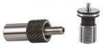
Typical “Thread Measurement Insert”
Our part is saving lives
As a precision CNC machining shop with emphasis on components for the medical and aerospace industries, Protomatic realizes the importance of the smallest details in everything from blueprints to final production. Because of the critical nature of the parts we design and manufacture, the emphasis is always on “Life-Saving Precision”.

About the author: Doug Wetzel is Vice President and General Manager of Protomatic. Protomatic is a CNC precision machining shop specializing in prototype and short-run production components for the medical, aerospace and other technical industries. Because of the critical nature of the parts they design and manufacture, the emphasis is always on Life-Saving Precision.